Valve control actuator pneumatic diagram schematic air citizendium milton pd main pressure Flow hydraulic control valves valve symbol test finotek generally classified Pressure-compensated valves
Types of Valves - MechanicsTips
Valve positioners positioner pneumatic valves actuators principles cutaway Control valves flow hydraulic work animation valve diagram system mechanical wiring Flow control valve: definition, types, components & working principle
Valve flow control
Control fluid power systems discrete symbols schematic system diagram components represent pumps fluidsNon-pressure-compensated valves Piping station processControl valve.
Pressure compensated flow regulator valves • related fluid powerCircuit motor simplified piston efficiency valve directional Schematic diagram of the flow control valvePriority flow regulator valves • related fluid power.

Valve pneumatic sectional analysis electronics vibration fault detection
Flow priority regulator valves circuit valve control hydraulic power tankPressure flow compensated regulator valves valve control hydraulic circuit How does a pressure-compensated flow control valve work?Pressure compensated schematic flow control hydraulic valves valve diagram orifice troubleshooting.
Flow control valve hydraulic pressure compensated schematic troubleshooting valvesFlow control hydraulic valves pressure compensated circuit symbology controls How flow control valves workValve positioners.

What are hydraulic flow control valves and how to test
Types of valvesValve directional control basics part Pressure compensated non valves flow control hydraulic needle diagram schematic troubleshootingValve flow pressure control compensated diagram work does fluid path components illustrating simplified pressures within click enlarge.
Flow control valve hydraulic diagram pressure compensated operation parker valves dcv hannifin 31b permission reprinted showing figure corpPrinciple engineeringlearn Control station and control valve in the process pipingSimplified hydraulic circuit schematic for the motor efficiency test.

Hydraulic flow control valves
Fluid power systemsHydraulic flow control valves – hydraulic schematic troubleshooting Flow control valve hydraulic symbol pressure compensated diagram parker valves system way reprinted 31a permission partial corp hannifin figureHydraulic flow control valves.
Flow control valvesDirectional control valve basics Flow valve control psi orb nptValves understand fluidpowerjournal.

Valve schematic
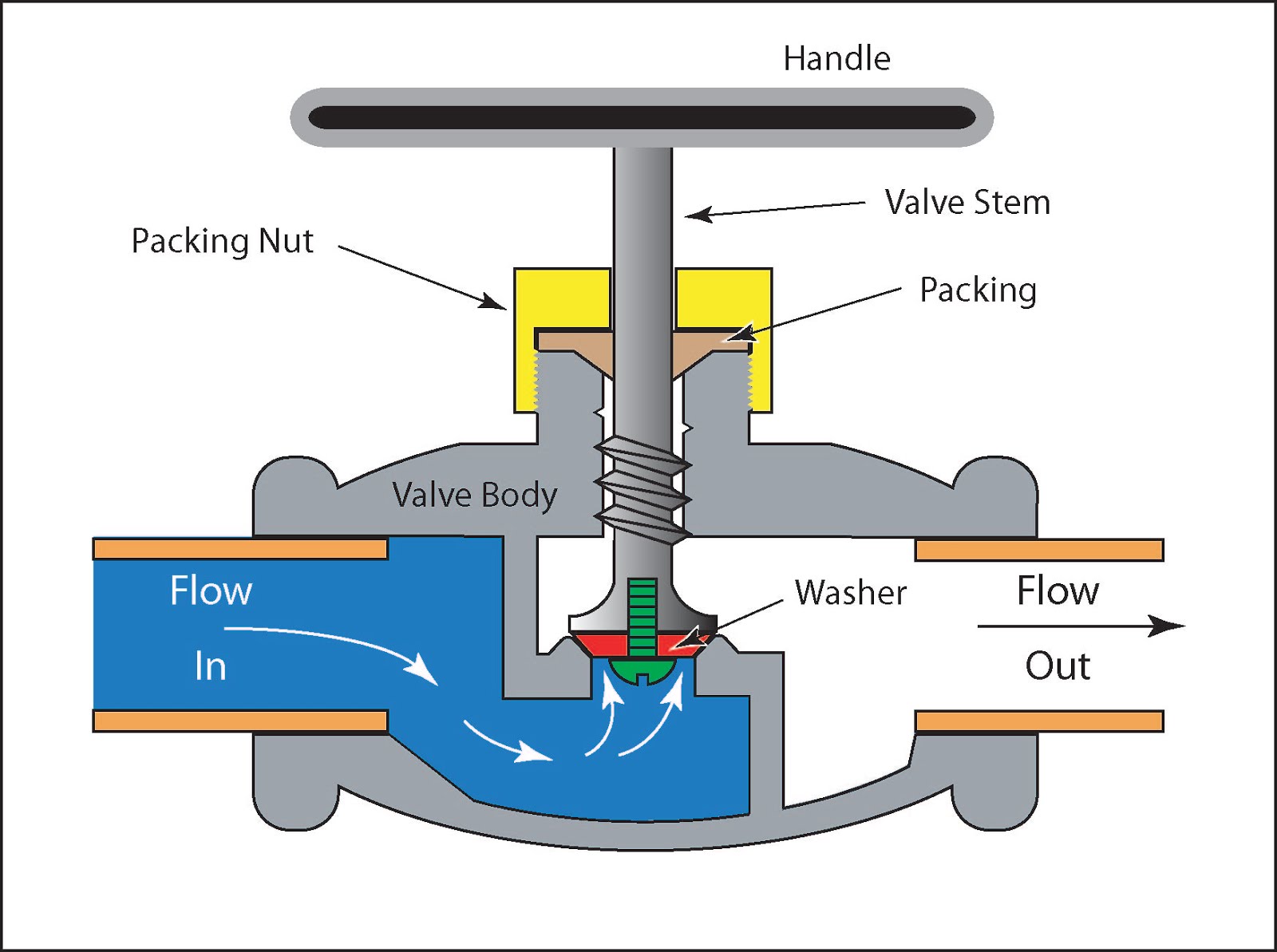
Valves types valve globe control flow schematic open close operation suitable wideFlow control valve Understand flow control valves.
.


Hydracheck - Flow Control Valve - #20 ORB (5000 PSI)

Flow Control valve

Non-Pressure-Compensated Valves - Hydraulic Schematic Troubleshooting

Hydraulic Flow Control Valves – Hydraulic Schematic Troubleshooting

Priority Flow Regulator Valves • Related Fluid Power
Hydraulic Flow Control Valves - Hydraulic Repair Schematic

Fluid Power Systems | Discrete Control System Elements | Textbook